Rowing Biomechanics
Kinematics of the Athlete's Body and the Oar in Rowing –
Nominal Performance and Stereotypical Errors
- Research Report
Austin Chang (1), Brandon Hsiao (1), Hao Lee(1), Simon Hoadley (2), Jacob Rosen (1)
(1) Bionics Lab Dept. of Mechanical and Aerospace Engineering, University of California, Los Angeles, 420 Westwood Plaza, Los Angeles, CA 90095-1597
(2) UCLA Head Coach Men’s Rowing, 2131 John Wooden Center, Los Angeles, CA 90095
Corresponding Author: Jacob Rosen (jacobrosen@ucla.edu)
Keywords: Rowing, Sculling, Biomechanics, Kinematics, Rowing Errors
PDF Copy of the report: [![]() RR_01]
RR_01]
Citing the report should include the following:
Austin Chang, Brandon Hsiao, Hao Lee, Simon Hoadley, Jacob Rosen, Kinematics of the Athlete's Body and the Oar in Rowing – Nominal Performance and Stereotypical Errors - Research Report, Bionica Lab, University of California, Los Angeles, 2021
Abstract
Introduction: Rowing is a cyclic and synchronized motion aiming to transfer the power from the athlete's body to the water via the boat and oars. By maximizing the efficiency of this power exchange, the speed of the boat is maximized as the athlete propels it forward. Acceptable variations from the nominal rowing motion are known as styles, but significant variations that limit the athlete/water power exchange are considered errors (faults). The aim of the study was to define and analyze these errors from the kinematics perspective.
Method: The study, conducted in a lab setting, used an ergometer and a motion capturing system. Thirteen errors including bladework errors and body position errors were emulated by a subject. The full body kinematics of this motion was recorded in real-time. Offline analysis compared each one of the errors with respect to a nominal rowing motion in phase space.
Results: The data suggest that the subsystems of the body including arms, back, and legs along with the coordinated way in which they are utilized in the various phases of the rowing motion including catch, drive, release, and recovery all contribute to the manifestation of errors. Furthermore, there is a cross influence between subsystems and the rowing phases. For example, a spatial error during the catch phase controlled by the arms is in part resulted from a temporal error generated by the legs. In addition, an error at one phase of the stroke may generate errors at other phases and vice versa.
Conclusions: Due to the complexity involved with the coordinated motions of the body’s various subsystems during the rowing motions, kinematic study of errors provide a deeper understanding of their root cause as well as insight into their correction. Eliminating spatial and temporal errors leads to increase of power transmission efficiency, boat speed, and potential avoidance of body injuries.
1. Introduction
Rowing is a cyclic motion that may be divided into two primary stages including the (1) drive, in which the blades interacts with the water as the athlete generates the propulsion force through this direct blade/water interaction and (2) the recovery, in which the blade does not touch the water and the propulsion force may be affected by the acceleration and deceleration of the body, oars, and boat. The drive and the recovery can be further divided into four phases including: (1) the catch, (2) the drive, (3) the release and (4) the recovery, which includes two transitional phases of catch and release in which the blade of the oar engages and disengages with the water during the two stages of the drive and recovery phases respectively [1,2,3, 23-27]. In each one of these phases, the athlete's body interacts with one or two oars held by the hands along with the boat itself (seat and foot stretcher). There are potentially two approaches to analyze and study the cyclic kinematics and dynamics motion of rowing that are applicable for both sculling and rowing. According to the first approach, the motion of the blade (the end effector of the oar) itself is studied exclusively. The premise of this approach is that if the blades follow a specific trajectory, then the athlete’s body follows the most effective kinematics and dynamics. According to the second approach if the kinematics and dynamics of the body is technically correct and efficient it leads to the ultimate trajectory of the blade, resulting in an effective delivery of power. Although each approach has its merit the ultimate approach is to synthesize between the two and analyze the entire system including the athlete, the oar, and the boat. The synthesized approach poses significant challenges as sensors have to be incorporated into the rowing boat and data have to be acquired on the water [4,5]. The reported study is focused solely on the kinematics of the athletes which allowed the study to be conducted in a lab setting using an ergometer (Concept II - Model D) [6-9] .
Although the four fundamental phases of the cyclic rowing motion along the sequence of events that should follow in each phase are well defined and qualitatively understood, variations from the common practice were developed and loosely defined as styles. Styles were developed over the years to accommodate specific variations between athlete groups regarding weight (heavyweight / lightweight), age (junior / senior), height, and gender, as well as boat types (1X, 2X,2+,2-,4X,4+,4-,8+) [10,11]. Known styles include: DDR Style, Rosenberg style, Adam style, Grinko style [25,26]. These styles are different in terms of the timing (temporal) for engaging the trunk and the legs as well as the relative position between the various body parts (spatial) [10]. More recently used styles relate to the temporal nature of the recovery phase (i.e. using the end of the release phase to accelerate/decelerate the athlete as he approaches the catch as well as the force profile of the drive phase) [11]. The different styles suggest that there is more than one single ultimate stroke pattern aiming to maximize the transfer of power from the athlete's body to the water for maximizing the speed of the boat. Furthermore, these styles are all within an acceptable framework. If any framework is violated, the motion is defined as an error or fault which is defined as improper derivatives of the correct rowing/sculling technique [1,2] that will most certainly lead to inefficient transfer of power resulting in a low boat speed.
Errors may be divided into three categories [1] including: (a) blade work errors (b) body position errors and (c) hand errors (Table 1). The list of errors and their specific definitions were compiled using a qualitative approach. The overarching aim of the reported study is to use the qualitative approach in studying rowing errors and to identify primary and secondary errors resulting from compensatory motions of the rower’s body. It is hypothesized that the subsystems of the body including arms, back, and legs along with the coordinated way in which they are utilized in the various phases of the rowing motion including catch, drive, release, and recovery all contribute to the manifestation of errors. Furthermore, it is hypothesized that there is a cross influence between subsystems and the rowing phases i.e. a spatial error during the catch phase controlled by the arms is in part resulted from a temporal error generated by the legs. In addition, It is hypothesized an error at one phase of the stroke may generate errors at other phases and vice versa contributing to a primary and secondary mechanisms that leads to an error.
Type |
No. |
Error (Fault) |
Symptom |
Causes |
Blade Work Errors |
1 |
Skying at the Catch |
As the blade approaches the water at the catch, it is lifted away from the water rather than being lowered in. |
a. Pushing the handle down with the hands right before the catch b. Overreaching at the catch c. dropping the head/body at the catch d. Too much height e. Blade too close to the water during the recovery. The act of squaring the blade requires a tap down which can lead to skying at the catch |
2 |
Looming |
The blade transverse too deep starting at the catch and during the entire stroke while water cover the entire blade |
a. Insufficient positive pitch b. The blade is not fully squared at the catch c. Excessive lift of arms and shoulder starting at the catch and continuing through the stroke. |
|
3 |
Backsplash |
Excessive water is sprayed by the edge of the blade towards the bow as the blade enters the water at the catch. |
a. slow entry of the blade into the water relative to the speed of the boat b. Incorrect direction of the blade entry |
|
4 |
Short Stroke |
The arc of the blade is short in comparison with other rowers, the stroke is shortened at the catch, the finish or both causing a shorter drive. |
a. Not allowing the body to follow the arc of the blade due to lack of reaching to compression position (catch) or leaning position (finish) stretching position. |
|
5 |
Two Part Stroke |
Speed during the drive is not consistent in acceleration. Blade accelerates at the beginning of the drive, decelerates in the middle, then proceeds to accelerate to the finish. |
a. Overgearing b. Uneven, inconsistent power c. Driving with the legs before blade is locked and submerged |
|
6 |
Washing Out |
Blade is lifted out of the water too early at the finished position. |
a. Drawing hands in too low at the finish b. Too much pitch c. Leaning away from the rigger at the finish d. Improper height of exertion |
|
Body Position Errors |
7 |
Overreaching (Catch) |
At the catch, the body slumps over the knees, consequently, the hands are closer to the feet. |
a. Not sliding to full compression b. Improper foot plate positioning c. Trying to inappropriately add length to the drive |
8 |
Arm Bending (Catch) |
Arms bent at the moment the blade enters the water |
a. Applying too much pressure with the arms at the catch b. Sliding forward on the recovery without full extension (recovery with bent arms) |
|
9 |
Slide Shooting |
Driving the seat back before the blade is in its proper catch position |
a. Legs are driving faster than the blade is being pulled by the hands b. Leg drives begins before blade is submerged in the water c. Stretching too much for length resulting in a weak upper body/back position d. Core and trunk not strong enough to maintain connection during leg drive |
|
10 |
Lack of Slide Control |
Experiencing rush and feels like each stroke is chasing after the next |
a. Poor rhythm |
|
11 |
Uneven Leg Drive |
During the drive portion of the stroke, the knees fail to come to a flattened, fully extended position at the simultaneously. |
a. Unequal pressure of the legs during the drive b. Poor balance |
|
12 |
Drawing the Body Up to the Oar Handle at the Finish |
Shoulders and head finish above or in front of oar blade rather than behind and the body does not pass vertical and instead hunches forward. |
a. Not maintaining the pressure on the stretch for the last part of the stroke b. Shoulders lack in power contribution at the finish. c. Prematurely pulling with the arms during the stroke |
|
13 |
Excessive Layback at the Finish |
Shoulders are positioned too far back from the hips at the finish |
a. Drawing with the arms once the leg drive had been completed and the seat is at the backstops b. Stretcher adjustment location incorrect c. Insufficient height of work |
Table 1: Errors (faults) and causes that will be examined in this study are summarized in the table and formulated based on [1,2]. Only a subset of the errors (13 out of 23 errors), could be emulated with an ergometer and included in this study. Methods (solutions) to correct the errors were provided in the original reference [1,2] but omitted from the table.
2. Methods
2.1 Experimental Setup and Protocol
Subject Definition - A 52 years old subject with 37 years of rowing experience in which 14 of those years were spent at the competitive level was recruited for the study. The subject has a stereotypical lightweight body type with the following physical dimensions: Height 1.79m with ground to hip joint length of 0.91m, ground to shoulder joint of 1.48m, and arms’ length (shoulder joint to fist cenet) of 0.63m .
Protocol - The subject was debriefed regarding every error as described in table 1. Although the rowing motion was conducted on an ergometer in which the interaction between the oar’s blade and the water no longer present, the subject was instructed to reproduce the rowing motion as similar as possible to how it would be conducted in a rowing boat. The subject repeated each error on the ergometer for 30 strokes and was recorded at a stroke rate of 26 strokes per min.
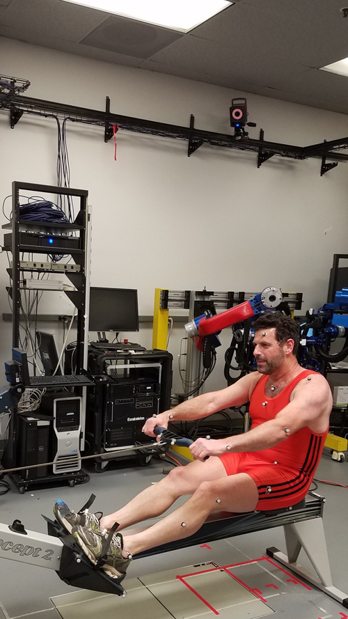
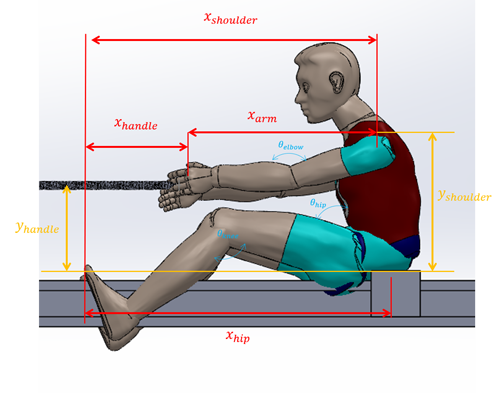
Equipment - An ergometer (Concept 2 - Model D) was placed at the center of a 15mx9m x3m open space equipped with motion capture system (Vicon - 12 Cameras). Reflective markers were placed on key anatomical structures based on the standard model (Fig. 1a). The position of all the markers were acquired by the motion capture system at a sampling rate of 100 Hz.
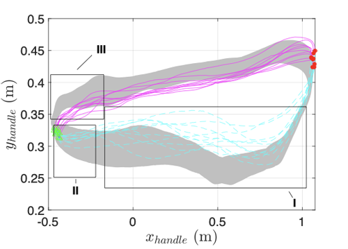
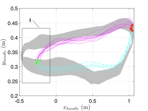
Post Processing Data Analysis - Out of the 30 recorded strokes, 14 consecutive strokes were isolated and further analyzed. The joint angles and angular velocities were calculated off-line using Vicon’s motion capture software. Data were exported from the motion capturing system and further post-processing analysis was performed using Matlab scripts. For the purpose of data presentation, the origin of the inertial coordinate system (the world coordinate system) was placed at a stationary point located at the foot stretcher underneath the Metatarsophalangeal joints (Fig.1b) and the axes alignment is depicted in Fig. 1b. Although the data were collected in a three dimensional space (3D), given the mirror image symmetric motion of the body during the rowing cycle with respect to the Sagittal plane, the data will be presented in the Sagittal (X-Y) plane using the parameters listed in Fig. 1b, with only one exception of the error associated with an uneven leg drive (Error No. 12) which affects the entire body in a 3D space. As part of the post-processing analysis, two distinct points were identified in each cyclic motion in which the value of the handle’s horizontal linear velocity switches sign and passes through a zero value. These two distinct points identify the transition points between: (1) the catch phase and (2) the release phase. A solid line connects the two points and represents parts of the catch and the drive phases whereas the release and the recovery phases are marked by a dashed line (See Fig. 2-16).
(a)
(b)
Figure 1: Experimental System (a) Overview of experimental setup - The subject, along with the reflective markers, rows on an ergometer (Concept 2) placed in a motion capturing setup (Vicon) (b) Schematics of the human body in a rowing position and the associated Cartesian and joint angle data that was further plotted and analyzed .
2.2 Primary and Secondary Expressions of the Errors – Definitions
From the kinematics perspective, the human body may be viewed as a multi-link (multi branched) serial mechanism where the torso, spine, and pelvis may be considered as its core base and the upper and lower extremities form its four multi linked serial mechanism. Each error typically has a prime expression that can be clearly associated with an incorrect motion of one or more body parts. However, given the redundant nature of the human body, secondary expressions of the errors may emerge. The secondary expressions of the errors may be a result of a compensatory mechanism that may or may not exist. In any case, they are more difficult to detect. For the cases in which secondary expressions were detected, this paper will discuss their kinematic expressions.
3. Results
3.1 Overview
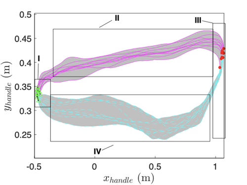
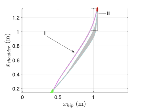
Given the cyclic dynamical nature of the rowing motion, the data are presented as phase portraits in the state space (phase space). There are two distinct points in which the horizontal velocity of the hand (oar) is reduced to zero. As the athlete changes the direction of the horizontal direction of the oar, this motion also signifies the beginning and the end of the stroke (mid catch and mid finish/release) and is marked in all the graphs by a hollowed triangle (catch) and solid circle (release). These two distinct points are connected by a solid line representing the drive phase and a dashed line depicting the recovery phase. The minimum and maximum values for the nominal motion are represented by a gray area that is also plotted as a background in all the plots for the errors in order to highlight the difference between the nominal and error motion.
3.2 Nominal Rowing Stroke
Motion Definition - The cyclic nominal rowing motion includes four phases: (1) the catch (2) the drive (3) the release/finish (4) the recovery. Given the synchronized nature of the rowing motion every part of the athlete’s body is involved in executing these phases either dynamically by a time dependent transition between body postures or statically by maintaining a specific body posture.
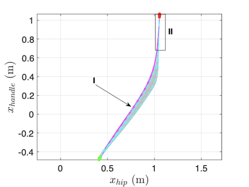
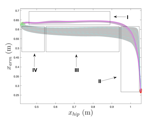
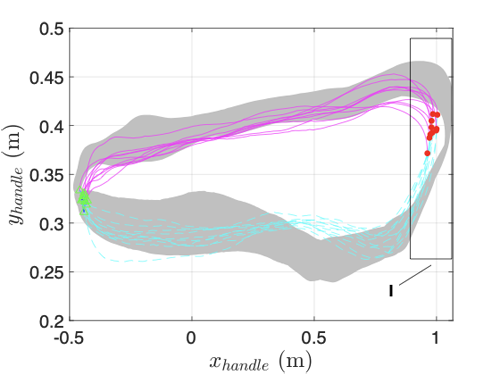
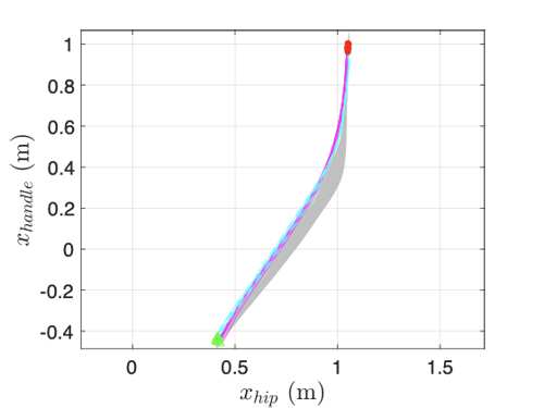
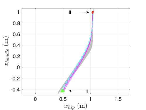
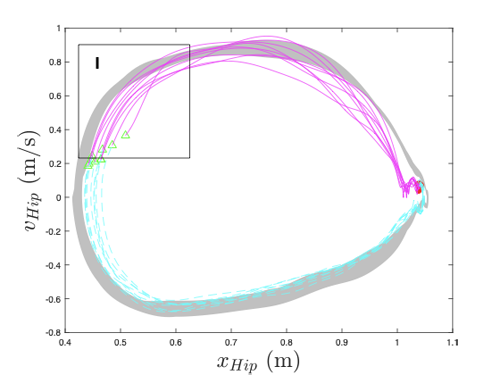
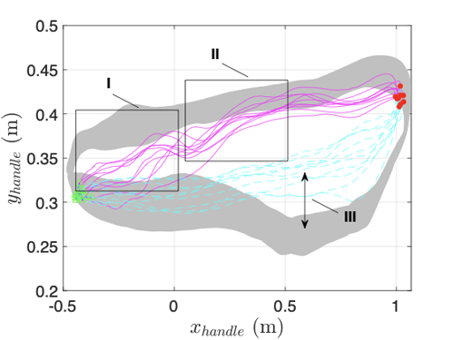
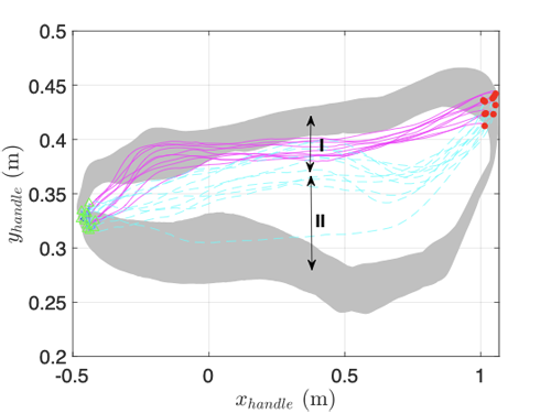
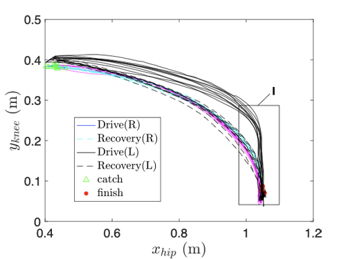
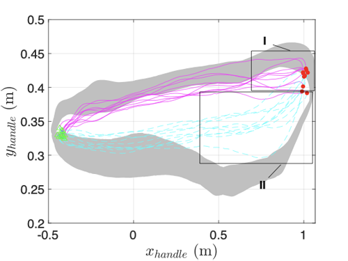
Kinematics of the Rowing Motion - The trajectory of the oar reperesented by the ergometer’s handle in the Sagittal plane is depicted in Fig 2a. The catch phase is identified as a rapid lift of the handle (0.049±0.008m) which is equivalent to the width of the oar’s blade with a minimal horizontal displacement (0.012±0.002m) - Fig. 2a- I. The drive phase is identified by a horizontal movement (1.40±0.01m) with minimal vertical motion of the handle (0.06±0.02m) - Fig. 2a- II. The release phase is identified by a rapid drop of the handle (0.03±0.01m) with a minimal horizontal displacement (0.11±0.01m) - Fig. 2a- III as the athelete aims to clear the blade from the water. Note that the horizontal displacement during the catch phase is shorter than the release phase. The recovery phase is identified by the continuous lowering of the handle at a rate lower than that of the release phase to a minimal value of 0.26±0.02m below the catching point followed by a gradual increase of the height of the handle as the athlete approaches the beginning of the catch - Fig. 2a- IV.
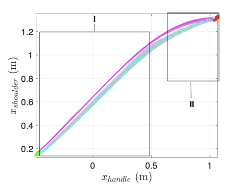
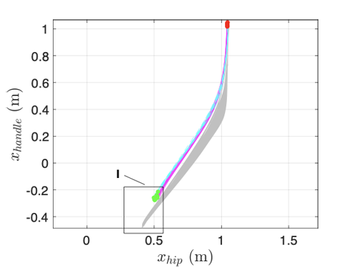
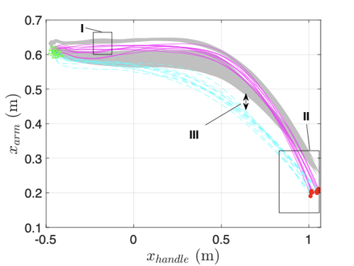
The synchronization of the horizontal flexion and extension of the arm and back as a function of the horizontal hip position in the Sagittal plane are depicted in Fig 2b and 2c respectively. During the first 75% of the drive phase the horizontal translation of both handle and the shoulder joint is linearly correlated with the horizontal translation of the hip - Fig 2b-I and 2c-I. During the last 25% of the drive the elbows flexed and the back extended simultaneously - Fig 2b-II and 2c-II. An identical sequence of motions took place during the recovery phase in a reversed order.
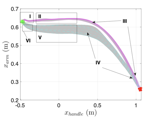
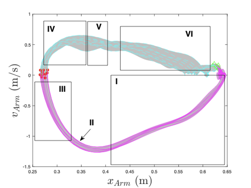
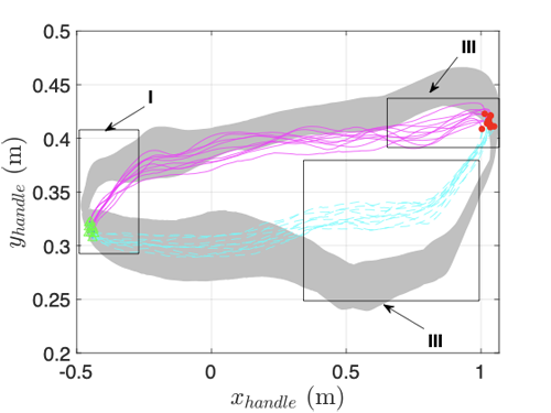
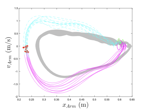
The dynamics of the elbow flexion and extension as expressed by the horizontal displacement between the handle and the shoulder joint as a function of the handle’s horizontal position as depicted in Fig. 2e. There is an increase of 0.007±0.005m in the distance between the handle and the shoulder joint at the beginning of the drive stage (Fig. 2e-I). This may occur due to scapular motion as the arms are subject to the tension buildup during the drive stage. This sudden change in the distance is later reduced back the anatomical distance of the arms and remain constant throughout 60% of the stroke (Fig. 2e-II). In the remaining 40% of the drive stage the elbow flex with an increasing rate till the end of the drive phase (Fig. 2e-III). The recovery follows a reverse order of events in which the elbow is first extended during the first 35% of the recovery stage (Fig. 2e-IV). However the arms remained partly stretched (0.59±0.02m), stretching the arms to 93% of their length during the following 60% of the recovery stage(Fig. 2e-V). This length represents the “rest length” of the arm where the flexor and extensor muscles of the elbows are in equilibrium. During the last 5% of the recovery the arms are stretched the last 7% of their full length mainly by the triceps muscles as the athlete prepares the arms for the catch phase (Fig. 2e-VI).
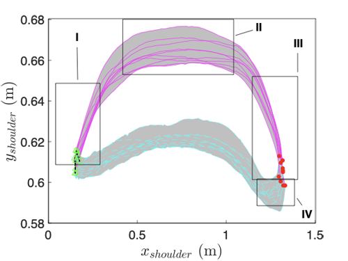
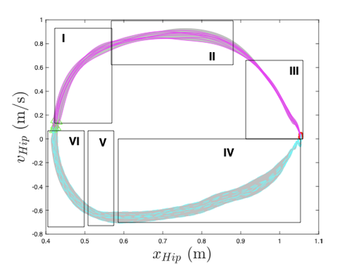
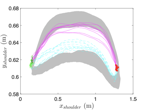
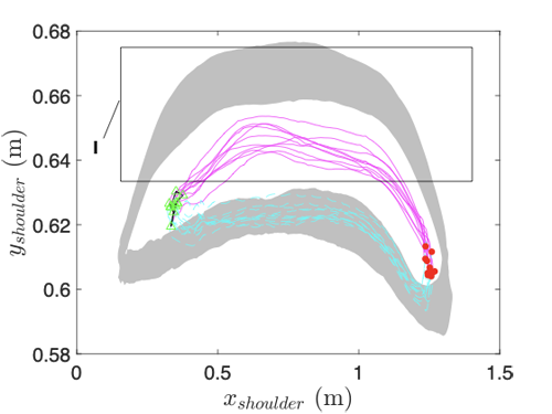
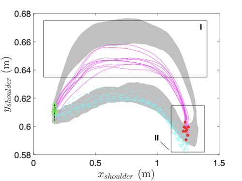
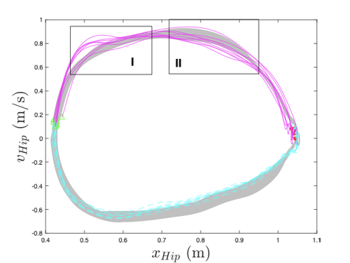
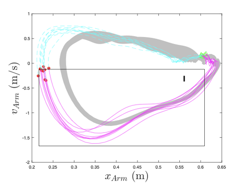
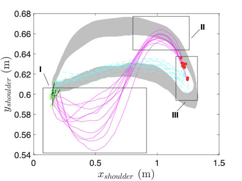
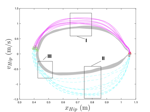
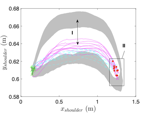
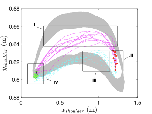
The trajectory of the shoulder joint’s center in the sagittal plane is depicted in Fig. 2f (note the difference between the scale of the X-axis and Y-axis). During the first 18% at the beginning as well as the end of the stroke, the center of the shoulder joint rose and dropped by 0.05m and 0.055m respectively indicating that the leaning back angle (Fig. 2f-III) at the end of the drive is larger than the leaning forward (Fig. 2f-I). The mid part of the drive phase is characterized by small changes of 0.02m in the shoulder joint position due to the rotation of the back with respect to the hip joint (Fig. 2f-I). The recovery follows a similar general behaviour, however the vertical displacement of the shoulder joint center is smaller with a maximal value of 0.010±0.004m above the catch position. This smaller value is due to flexion of the back during the recovery stage compared to the drive stage. Furthermore, the shoulder at the beginning of the recovery phase continued to drop below the vertical position by an additional 0.010±0.006m to facilitate the release of the handle which translates to clearing the blade off the water while rowing in a boat (2f-IV). The relationship between the horizontal arm length and the hip position is depicted in Fig. 2e. During the drive through release phase, the arms remain fully stretched for 90% of the hip displacement (Fig. 2e-I) followed by elbow flexion during the remaining 10% of the hip displacement (Fig. 2e-II). The elbows is then extended similarly during the first 10% hip of the hip displacement and remained partly flexed i.e. 88% of a full arm length for the following 57% of the hip displacement (Fig. 2e-III). The last 33% of the hip displacement of the elbow extends gradually to fully stretched arms prior to the catch. The position-velocity phase diagrams of the arm length and hip position are depicted in Fig. 2h and 2i respectively (note the reverse order of Fig. 2h). During the stroke phase both the arms and the hips accelerate during the beginning of the stroke (Fig. 2h-I , Fig. 2i-I) reaching a peak velocity (Fig. 2h-II , Fig. 2i-II) and then decelerate toward the end of the drive (Fig. 2h-III, Fig. 2i-III). Note that the velocity of the arms has a distinctive shorter peak (Fig. 2h-II). The max velocity of the hip is maintained for a longer distance during the stroke (Fig. 2i-II). A similar behavior is exhibited for both parameters during the recovery with a single distinctive velocity peak for both parameters (Fig. 2h-IV , Fig. 2i-IV).
(a)
(b)
(c)
(d)
(e)
(f)
(g)
(h)
(i)
Figure 2: Nominal Rowing Stroke. (a) Y_handle = f(X_handle). (b) X_shoulder = f(X_hip). (c) X_handle = f(X_hip). (d) X_shoulder = f(X_handle). (e) X_arm = f(X_handle). Y_shoulder= f(X_shoulder). (g)Xarm = f(X_hip). (h) V_arm = f(X_arm).
V_hip = f(X_hip).
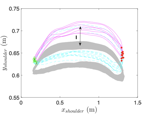
3.3 Error 1 – Skying at the Catch
Error Definition – Skying at the catch takes place during the recovery portion of the stroke. It starts mid-recovery and continues till the blade is placed in the water. The blade of the oar is lifted higher as the hands push the handle down below its nominal height.
Primary Expression – Skying at the catch is expressed by the vertical displacement decrease of the handle by 0.0705±0.004m (12%) compared to the nominal catch position (Fig. 3a-I). As a result, the blade is not engaged with the water at the beginning of the stroke phase such that the effective stroke in which the blade is below the waterline and propelled the boat forward is reduced by 42% (Fig. 3a-II). Despite the fact that the error refers specifically to the end of the recovery, the data suggest that skying is a result of a significantly different recovery trajectory (Fig. 3a-III). At the beginning of the recovery the handle remains high and is gradually decreased towards the catch phase. This trajectory is substantially different than the nominal U-shaped trajectory of the handle during the recovery in the nominal motion.
Secondary Expression - Beyond the effective decrease in the effective stroke length due to skying, the entire stroke length— measured by the horizontal handle displacement—is shortened at the catch by 12.4% (0.076±0.005m) - Fig. 3b-I. Furthermore, skying at the catch is also associated with an increase in the vertical shoulder displacement by 0.025±0.003m throughout the entire recovery phase (Fig. 3c-I) in part due to the anticipation of reducing the height of the hand.
(a)
(b)
(c)
Figure 3: Skying at the Catch. (a) Yhandle= f((Xhandle). (b) Xarm= f(Xhip). (c) Yshoulder= f(Xshoulder)
3.4 Error 2 – Looming
Error Definition - Looming takes place during the drive portion of the stroke starting at the catch and continues during the entire drive where the blade is pushed too deep into the water with respect to the waterline while allowing water to flow over (loom) the blade. Pushing the blade below the waterline is done by lifting the handle above the nominal height.
Primary Expression – Driving the blade deep below the waterline is expressed by a high vertical position of the handle with an average increase of 0.10±0.02m compared to the nominal position during the drive phase (Fig. 6a-I). Moreover, the variability (i.e. standard deviation) of the vertical position during the looming stroke phase is larger by 24.3% (0.03m) compared to the nominal stroke phase.
Secondary Expression – An increase of the handle’s height is observed during the first 60% of the recovery phase (Fig. 6a-II). Furthermore, as a result of the looming during the drive phase the height of the handle during the recovery remains constant as opposed to the variation of the height during the nominal motion in which the recovery starts low, aiming to clear the blade from the water and gradually increase as the rower approaches the catch. In addition, the stroke length is typically shorter by 4% (0.05 m) as a result of the looming at the catch point whereas the finish point remained unchanged. Looming is also associated with an increase of the shoulder horizontal position (Fig. 6b-I) as well as vertical position (Fig. 6c) through stroke and the recovery stages. Although the horizontal positions of the shoulder and the hip are similar with and without looming at the end of the drive phase, the rate in which the shoulder moves forward following the blade release phase from the water is quicker in the nominal stroke compared to looming. In addition, looming is facilitated in part by a raised shoulder joint vertically by 0.04±0.01m which was a 5.3% increase in height. Both effects causing the blade to transverse too low with respect to the waterline.
(a)
(b)
(c)
Figure 4. Looming. (a) Yhandle = f(Xhandle). (b) Xshoulder = f(Xhip). (c) Yshoulder = f(Xshoulder).
3.5 Error 3 – Backsplash
Error Definition – Backsplash error takes place when excessive water is sprayed by the edge of the blade towards the bow (front of the boat) as the blade enters the water at the catch. Backsplashing is caused by a slow entry of the blade into the water relative to the speed of the boat and/or incorrect direction of blade entry. Note that in the current study, given the use of the ergometer, the oar rotation is not conducted and measured.
Primary Expression – Backsplashing takes place at several phases: (1) during the entire recovery phase as the handle of the oar is kept relatively high compared to nominal motion which leads to smaller distance between the blade and the water (Fig. 5a - I); (2) at the end of the recovery phase, the short distance between the blade and the waterline becomes critical as the blade is rotated perpendicular to the waterline as a preparation to the catch phase (Fig. 5a - II); (3) during the catch phase in which there is a slow introduction of the blade to the waterline (Fig. 5a - III). Any or all of these factors lead to backsplash.
Secondary Expression - A byproduct of a high position of the handle (low position of the blade) during the recovery and the catch-phase is associated with a higher vertical position of the shoulder joint center as well as a lower vertical position of the shoulder joint center during the stroke phase (Fig. 5b).
(a)
(b)
Figure 5. Backsplash. (a) Yhandle = f(Xhandle). (b) Yshoulder = f(Xshoulder).
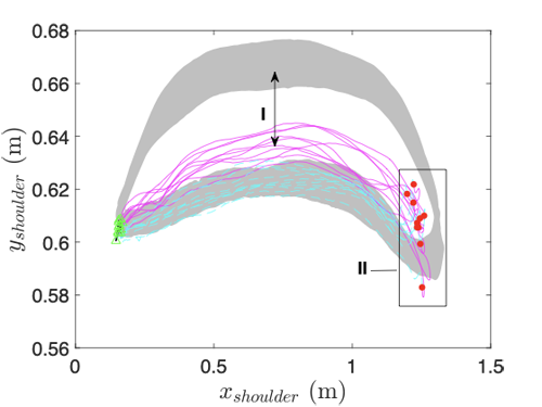
3.6 Error 4 – Short Stroke (Beginning/End)
Error Definition – The arc of the blade is short in comparison with other rowers, the stroke is shortened at the catch, the finish, or both causing a shorter drive. At the beginning of the stroke the catch may be brief, failing to stretch the arms and fully flex the hips and knees joints. At the end of stroke, the hand may not be fully flexed and legs may not be fully extended followed by minimal exertion of the back.
Primary Expression – The stroke shortening is expressed at the front end of the stroke when the athlete slides forward during the recovery phase towards the catch phase and stops short, prematurely. This error leads to a shortening of 23% (0.22±0.02) of the nominal stroke length (Fig. 6a - I). The stroke shortening is expressed at the back end of the stroke as the athlete goes through the stroke phase and terminate 9% (0.07±0.01) shorter than the nominal stroke length (Fig. 6b - I).
Secondary Expression - A common phenomena associated with shortening of the stroke length at the beginning and the end of the stroke phase is a lower vertical (y) position of the shoulder joint during the stroke phase by 0.016±0.004m. However the mechanisms involved in shortening the stroke at the front end and the back end are different. At the front end, the stroke is shortened primarily by a shorter translation of the hip (seat) - Fig. 6e - I whereas at the back end, the stroke shortens by a lack of back leaning as manifested graphically by the shorter horizontal translation of the shoulder joint - Fig. 6d - II. It should be noted that the translation of the seat was identical to the nominal motion - Fig. 6f.
(a)
(b)
(c)
(d)
(e)
(f)
Figure 6. Short Stroke Beginning[Bg]/End[Ed] - (a) Yhandle = f(Xhandle) [Bg]. (b)Yhandle = f(Xhandle) [Ed]. (c) Yshoulder = f(Xshoulder) [Bg]. (d) Yshoulder = f(Xshoulder) [Ed]. (e) Xhandle = f(Xhip) [Bg]. (f) Xhandle = f(Xhip) [Ed].
3.7 Error 5 – Two Part Stroke
Error Definition – A two part stroke takes place during the stroke phase. The blade accelerates at the beginning of the stroke, decelerates in the middle, then proceeds to accelerate to the finish. Thus, the acceleration is not consistent due to uneven inconsistent power exertion and improper leg drive timing.
Primary Expression – The two-part stroke is expressed graphically in Fig. 7a and depicted as a two horizontal (x) velocity peaks (Fig. 7a-I and Fig. 7a-II) of the hip joint (horizontal velocity of the seat) with the first peak at 20% of the seat horizontal (x) displacement and the second peak in the range of 43% to 58% of the seat horizontal (x) displacement. This result may be compared to the nominal motion in which the velocity reaches the peak at 58% of the seat horizontal displacement. This phenomenon is also associated with a large variation of the arm velocity compared to the nominal motion Fig. 7b-I. Since the athlete's body may be viewed as a serial chain starting at the foot stretcher and ends at the oar handle, any weak link between these two points may lead to a two-part stroke by failing to maintain the required power transmission.
Secondary Expression - The two part stroke is associated with: (1) slow catch phase indicated by a slower vertical lift of the handle (Fig. 7c-I); (2) early and premature release, expressed in reduction of the vertical handle position at the end of the stroke phase (Fig. 7c-II); (3) unclean release and recovery manifested at high handle position during 50% of the recovery phase (Fig. 7c-III) (4) decreased vertical position (y) of the shoulder joint (Fig. 7d-I) and (5) limited extension of the back at the end of the stroke phase (Fig. 7d-II). All of the above effects contributed to effective shortening of the stroke length.
(a)
(b)
(c)
(d)
Figure 7: Two Part Stroke. (a) Vhip = f(Xhip). (b) Varm= f(Xarm). (c) Yhandle= f(Xhandle). (d) Yshoulder= f(Xshoulder).
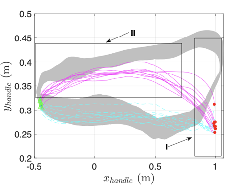
3.8 Error 6 – Washing Out
Error Definition – Washing out takes place at the finish of the stroke when the blade is lifted out of the water prematurely. This occurs as the hands are drawn in too low and finish at an improper height.
Primary Expression – Lifting of the blade at the end of the stroke is depicted in Fig. 8a-I as the vertical (y) position of the handle is lowered by 0.11±0.02 m with respect to the nominal motion.
Secondary Expression - Although the error associated with lifting the blade out of the water prematurely is related to the end of the stroke, the data specifically suggest that the blade is not properly engaged with the water throughout the entire stroke phase. The vertical trajectory of the handle is lower than the nominal motion trajectory all along the the stroke phase Fig. 8a-II. The low vertical handle position is associated with a low vertical (y) shoulder joint position throughout the entire stroke phase (Fig. 8b-I) along with a shorter horizontal (x) translation of 0.068±0.004 m at the end of the stroke phase (Fig. 8b-II).
(a)
(b)
Figure 8: Washing Out. (a) Yhandle = f(Xhandle). (b) Yshoulder = f(Xshoulder).
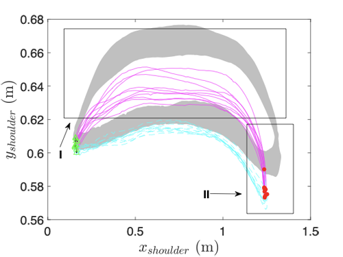
3.9 Error 7 – Overreaching (Catch)
Error Definition – Overreaching, also known as reaching for longer stroke length, takes place during the front end part of the recovery, as the athlete overreaches for more length at the catch by overextending the handle position along with a shoulder slump.
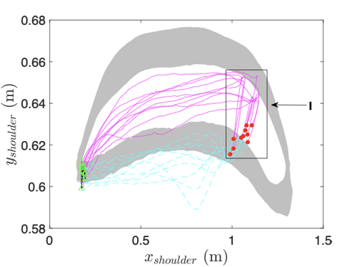
Primary Expression – Slumping forward at the catch leads to an average decrease of the vertical (y) position of the handle at the beginning of the catch of 0.089±0.009m compared to the nominal position (Fig. 12a). Moreover, in spite of the athlete's attempt to increase the length of the stroke, the horizontal (x) displacement of the handle was reduced to 90% compared to the nominal stroke length (Fig. 12a). This same behavior is exhibited in the shoulder’s drop in vertical (y) position with an average decrease of 0.06±0.01m compared to the nominal position (Fig. 12b-I). Moreover, the variability (i.e. standard deviation) of the vertical position of the shoulder joint during the catch-phase (0.01m) is smaller by 38.6% compared to the respective nominal stroke phase (0.005m).
Secondary Expression - A decreased hip displacement reduction of the hip flexion is observed at the catch position (Fig. 12c-I). In addition, the overall stroke based on the displacement of the hip is shorter by 16% (0.1072 m) resulting from an attempt to move the upper body forward while compromising hip flexion. This is one of the leading factors that led to an overall shorter stroke length.

(a)
(b)
(c)
Figure 9: Overreaching. (a) Yhandle = f(Xhandle). (b) Yshoulder = f(Xshoulder). (c) Xhandle = f(Xhip).
3.10 Error 8 - Arm Bending (Catch)
Error Definition –Arm Bending (Catch) error occurs during the recovery phase. It starts from mid-recovery up to the catch position, as well as during the first phase of the drive phase in which the arms fail to straighten out before raising up the handle. The blade is placed into the water followed by pulling the oar with bent arms during initial drive of the stroke.
Primary Expression – The error associated with approaching the catch phase with partly flexed elbows or/and bending / flexing the elbow during the catching phase - Fig 10a-I. However this error was also expressed during most of the recovery and the drive phases (Fig 10a-II) in which the horizontal arm length (x) defined as the distance between the shoulder joint and the handle is reduced to 91% (0.0541±0.04m) of it is nominal length when the arm is fully stretched.
Secondary Expression - Bending the arms led to a slower catch-phase (Fig 10b-I) as well as a lower vertical position of the handle with respect to the nominal phase (Fig 10b-II). This in turn led to a premature engagement of the blade from the water during the release phase. In addition, the vertical handle position remains higher than the reference motion (Fig 10b-III) which runs the risk of unwanted interactions between the blade and the water during the recovery phase which is when the boat is the least stable. Bending the arms also indirectly affects the position of the shoulder joint. In general, the vertical position of the shoulder joint was lower during the entire stroke phase by an average of 0.013 ±0.007m (Fig 10c-I) and during the second half of the recovery phase by an average of 0.013 ±0.005m (Fig 10c-II). The horizontal displacement of the shoulder joint is reduced by 0.05±0.02m (Fig 10c-III) indicating that the back leans less at the end of the stroke compared to the nominal motion.
(a)
(b)
(c)
Figure 10. Arm Bending (Catch). (a) Xarm = f(Xhandle). (b) Yhandle = f(Xhandle). (c) Yshoulder = f(Xshoulder).
3.11 Error 9 – Slide Shooting
Error Definition – Driving the seat back during the drive at a much faster rate than the rate at which the handle moves back during the drive.
Primary Expression – The rapid seat movement at the beginning of the stroke along with the peak of the horizontal velocity of the hip joint (seat) is a result of the movement of the seat out of synchronization with the handle (Fig. 11 a-I). The implication of this error is that the power generated by the legs at the beginning of the stroke are not transmitted via the back and the arms to the handle.
Secondary Expression - The rapid movement of the seat at the catch phase followed by the beginning of the drive phase is not coordinated with the movement of the handle. This results in a significant decrease of the shoulder joint’s vertical (y) position to a height that is even lower than its vertical position during the recovery phase (Fig. 11 b-I). The decrease in the vertical position of the shoulder joint is a result of hyperflexion of the back as the seat is moving forward and the handle is lagging behind. This results in the lowering of the handle. It starts during the catch and is followed by the first half of the drive phase and delays the engagement of the blade with the water during the catch (Fig. 11 c-I). Despite the handle and shoulder joint positions recovering their nominal drive phase positions (Fig. 11 b-II, Fig. 11 c-II), the back does not sufficiently lean backward compared to the nominal motion (Fig. 11 b-III). Furthermore, a relatively high handle position is maintained, leading to a lower blade position at the beginning of the recovery phase (Fig. 11 c-III).
(a)
(b)
(c)
Figure 11. Slide Shooting. (a) Vhip = f(Xhip). (b) Yshoulder = f(Xshoulder). (c) Yhandle = f(Xhandle).
3.12 Error 10 – Lack of Slide Control
Error Definition – The lack of slide control refers to an inappropriate rhythm ratio between the drive and recovery phases in which the rower experiences a rushing tempo and feels as if each stroke is chasing after the next. The poor rhythm is a result of poor temporal body control.
Primary Expression – The lack of slide control is expressed by a higher horizontal (x) hip joint / seat speed which increases by 50% with respect to the nominal motions (Fig 12 a-I and a-II) at both the stroke and the recovery phases. Moreover, the peak velocity of the seat appears early during the recovery phase (Fig 12 a-II) compared to the nominal motion for which the peak velocity appears as the athlete approaches the catch phase (Fig 12 a-III). Furthermore, the arm’s horizontal (x) velocity (i.e. elbow joint flexion/extension peak speed) increases by 80% during the stroke phase and by 36% during the recovery phase. The lack of slide control damages the time ratios between the stroke and the recovery phases. Rushing through the recovery phase does not allow the body the necessary recovery period and leads to an accelerated fatigue.
(a)
(b)
(c)
(d)
(e)
Figure 12. Lack of Slide Control. (a) Vhip = f(Xhip). (b) Varm = f(Xarm). (c) Yhandle = f(Xhandle). (d) Yshoulder = f(Xshoulder). (e) Xarm = f(Xhandle).
3.13 Error 11 – Uneven Leg Driving Throughout the Stroke
Error Definition – The left and the right knee joints do not extend equally during the stroke phase starting at the catch and continues during the entire drive where the left knee and the right knee fail to straighten out simultaneously, resulting from unequal application of force on the foot stretcher and/or lack of balance of the rower. Additional uneven movements such as unsynchronized ankle flexion can also occur.
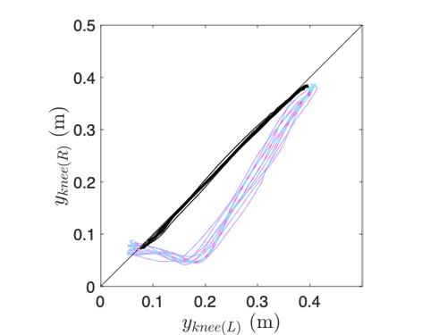
Primary Expression – The uneven extension of the left and the right knees is depicted in terms of the vertical displacement of the knee joints in Fig. 13 a,b. When the left and the right knees are extended simultaneously and equally, plotting them one against the other should generate a straight line at an angle of 45 deg in an equal axes plot (Fig. 13-a). While a major deviation from this line indicates unequal flexion/extension of the knees, a minor deviation may be a result of naturally anatomically uneven leg lengths. The data indicates that the right knee is extended faster than the left knee starting at the catch phase and continues through the drive phase. Since the subject under study has close to equal leg length, there is a rapid change at the end of the stroke phase in which the left knee is rapidly extended to match the right knee (Fig. 13 a-I, Fig. 13 b-I). This rapid change of the left knee angle is resulted in a twist of the pelvis.
Secondary Expression - A decrease in vertical (y) displacement of the shoulder joint is observed throughout the drive phase (0.024±0.005 m) - Fig. 13 c-I. This is followed by a higher release point (0.029±0.008m) - Fig. 13 c-II, and continued by an increase in vertical (y) displacement of the shoulder joint at the beginning of the recovery phase 0.008±0.005 m (Fig. 13 c-III). A decrease in horizontal (x) displacement of the shoulder joint by 13% is observed when compared to the nominal motion. This change is more pronounced when examining the leaning of the back at the release phase (Fig. 13 c-III) compared to the catching phase (Fig. 13 c-IV). The process of equalizing the straightening of the legs affected the leaning process of the back. The trajectory of the handle is lower primarily at the end of the stroke (Fig. 13 d-I) accompanied by a higher vertical position of the handle during the first half of the recovery phase. Uneven leg drive is associated with poor body positioning which leads to a shorter stroke and unclean release of the blade during the recovery.
(a)
(b)
(c)
(d)
Figure 13: Uneven Leg Driving Throughout the Stroke (a) Yknee(R) = f(Yknee(L)). (b) Yknee(L/R) = f(Xhip). (c) Yshoulder = f(Xshoulder). (d) Yshoulder = f(Xhandle) (black bolded line represents the nominal motion).
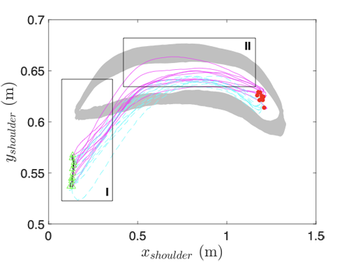
3.14 Error 12 – Drawing the Body Up to the Oar Handle at the Finish
Error Definition –Drawing the Body Up to the Oar Handle at the finish takes place at the finish position of the stroke, in which the shoulders and head are in front of the oar blade rather than behind. The body does not pass vertical and instead hunches forward. Causing hip angle, shoulders, and head displacements to be below the nominal body displacements.
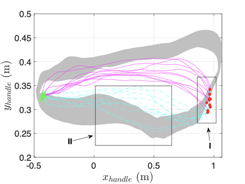
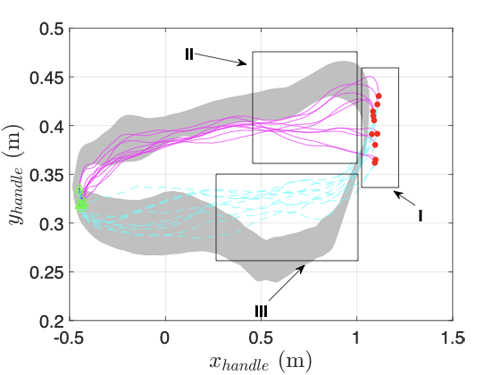
Primary Expression – A rapid change in both the horizontal (x) and vertical (y) position of the shoulder joint is detected at the end of the stroke as the upper body approaches the handle and flexes (hunch) over it (Fig. 14a-I)
Secondary Expression - The back flexion as opposed to the proper back extension at the end of the stroke leads to two phenomena: (1) the handle is dropped significantly by 0.10±0.02 m from a chest level at the end of the stroke (Figure 14b-I). It starts at the last 25% of the drive therefore decreasing the athlete's ability to apply the proper horizontal force to propel the boat forward as the blade gradually decreases its contact with the water. Furthermore, during the release phase, followed by the first 60% of the recovery phase, the handle is higher by 0.06±0.03 m above the nominal height (Figure 14b-II). A higher handle height leads to lower blade height with respect to the waterline at a very critical and unstable phase of the stroke.
(a)
(b)
Figure 14: (a) Yshoulder = f(Xshoulder). (b) Yhandle = f(Xhandle).
3.15 Error 13 – Excessive Layback at the Finish
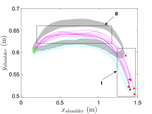
Error Definition – Shoulders are positioned too far back from the hips at the finish of the stroke phase as the back is overly extended.
Primary Expression – The over extension of the back at the end of the drive is depicted in Fig. 15a-I. The center of the shoulder joint moves 0.13±0.03 m horizontally (x) and 0.08±0.01m vertically (y) beyond the nominal position at the end of the stroke as the angle between the back and the vertical axes increased. In spite of this extensive translation of the back, the horizontal stroke length (x) was only 0.05±0.01 m longer than the nominal stroke length, which translated into 4.2% increase stroke length (Fig. 15b-I)
Secondary Expression - The over extension of the back at the end of the stroke has several major secondary effects: (1) The vertical (y) position of the shoulder joint center was lower throughout the entire drive phase by 0.023 ±0.004m (Fig. 15a-II) whereas the position during the recovery phase was within the min/max values of the nominal movement; (2) The vertical position of the handle during the last 25% of the stroke phase was lower on average by 0.04 ±0.02 m (Fig. 15b-II) which in turn lead to a premature disengagement of the blade from the water limiting the propulsion force generated by the athlete during the drive phase; (3) The vertical position of the handle during the first 50% of the recovery phase was higher on average by 0.06 ±0.01m (Fig. 15a-III) which in turn lowered the blade with respect to the water line and subjected the blade to unintended interactions with the water during an unstable moment of the recovery. Both of the last two effects result from the lowering of the chest which is used as an anatomical reference point during the process of leaning back.
(a)
(b)
Figure 15. Excessive Layback at the Finish. (a) Yshoulder = f(Xshoulder). (b) Yhandle = f(Xhandle).
4. Conclusions and Discussion
This study provides a quantitative insight into the kinematics of the nominal rowing motion as well as 13 various errors out of 23 stereotypical errors [1,2] divided into blade work errors (6 errors) and Body position errors (7 errors) - Table 1. The nominal rowing motion aims to maximize the propulsion force, therefore maximizing the speed of the rowing boat. Variation of the rowing motion i.e. styles may be athlete specific, however significant deviation from the nominal rowing motion is defined as an error. An error may cause three major effects: (1) reduce the propulsion force by affecting the efficiency in which the athlete's body transmits power to the boat and (2) create a physical injury to the athlete, although injuries may also develop due to the repetitive nature of the motion and not necessarily from a specific error [12-22] (3) limited ability to synchronize the the sequence of the stroke with teammates in the same crew .
In the context of the rowing motion, the athlete's body can be divided into three subsystems including: (1) hands & arms, (2) back (3) legs & feet. The body can be viewed as a highly redundant serial mechanism that interacts with the boat/oar at three interfaces: the handle/hands, seat/pelvis, and footstretchers/feet. Among all the errors under study, the primary error is typically identified in one of the subsystems. However secondary errors appear in other subsystems. For example: (1) uncontrolled motion of the seat via the legs (errors 9,10,11) affects the upper body and hands; (2) excessive or minimized back motion (errors 2,4,7,12,13) affect the trajectory of the hands and therefore change the kinematics of the oar’s handle shortening the length of the stroke; (3) handle’s trajectory control via the hands and the subsequent interaction of the blade with the water (errors 1,3,5,6,8) are affected by all three subsystems. Temporal interruption of the rowing cycle (errors 5,9,10) led to a decrease in the effective length of the stroke. The shortening was expressed by a slow catch, premature release, and lack of leaning back, as well as a higher vertical handle position (blade close to the waterline) at the beginning of the recovery phase. In general, the data suggest that errors that take place at specific parts of the stroke (e.g. the catch phase) influence other phases of the stroke e.g. drive, release and recovery and vice versa. In spite of the methodological approach of dividing the cyclic rowing motion into four phases, they are all affected by each other.
In conclusion, the data suggest an intricate mechanism involving multiple subsystems which lead to the reported errors under study. As coaches aim to correct errors made by the athlete, attempts have to be made to identify the root causes of the errors and not just their expressions since the root cause mechanism is the key to eliminate the error. The right methodological approach in correcting the error is not just to explain to the athlete what is done wrong but what should be done differently to eliminate the error.
References
[1] Steven Redgrave, Complete Book of Rowing, Partridge Press, 1992
[2] Wolfgang Fritsch, Rowing – Technique Fitness Leisure, Meyer & Meyer Sport, 2000
[3] Volker Nolte (ed), Rowing Fast, Human Kinetics, 2005
[4] Douglas H. Lamb, A kinematic comparison of ergometer and on-water rowing, The American journal of sports medicine, Volume: 17 issue: 3, page(s): 367-373, 1989
[5] V. Fohanno, P.J. Sinclair, R. Smith & F. Colloud (2013) How to reconstruct
athlete movement during outdoor rowing? A pilot study, Computer Methods in Biomechanics and Biomedical Engineering, 16:sup1, 95-96,
[6] Stephan Bosch et. al, Analysis of indoor rowing motion using wearable inertial sensors, BODYNETS 2015, September 28-30, Sydney, Australia
[7] B Cutler, T Merritt, T Eger, A Godwin, Using Peak Vicon data to drive Classic JACK animation for the comparison of low back loads experienced during para-rowing, Int. J. Human Factors Modelling and Simulation, Vol. 5, No. 2, 2015
[8] Nicolas Découfour, Franck Barbier, Philippe Pudlo, Philippe Gorce,
Forces Applied on Rowing Ergometer Concept2®: a Kinetic Approach for Development, The Engineering of Sport 7, 2008 - Springer
[9] Charence Wong, Zhi-Qiang Zhang, Benny Lo, and Guang-Zhong Yang, Wearable Sensing for Solid Biomechanics: A Review, IEEE SENSORS JOURNAL, VOL. 15, NO. 5, MAY 2015
[10] Klavora P. 1977. Three predominant styles: the Adam style; the DDR style; the Rosenberg style. Catch (Ottawa), 9, 13.
[11] Valery Kleshnev, Rowing Biomechanics Newsletter, Vol. 6 No.60 March 2006
[12] JS Rumball, CM Lebrun, SR Di Ciacca, K Orlando, Rowing injuries - Sports medicine, 35 (6): 537-555, 2005 - Springer
[13] Roy J. Shephard (1998) Science and medicine of rowing: A review, Journal of Sports Sciences, 16:7, 603-620,
[14] Jane S. Thornton, Anders Vinther, Fiona Wilson, Constance M. Lebrun,
Mike Wilkinson, Stephen R. Di Ciacca, Karen Orlando, Tomislav Smoljanovic, Rowing Injuries: An Updated Review, Sports Med (2017) 47:641–661
[15] Wilson, F., Gissane, C., McGregor, A. (2014). Ergometer training volume and previous injury predict back pain in rowing; strategies for injury prevention and rehabilitation. British Journal of Sports Medicine, 48 1534-1537. doi: 10.1136/bjsports-2014-093968
[16] Yang, J., Tibbetts, A.S., Covassin, T., Cheng, G., Nayar, S., Heiden, E. (2012). Epidemiology of overuse and acute injuries among competitive collegiate athletes. Journal of Athletic Training, 47(2), 198-204.
[17] Buckeridge, E. M., Bull, A.M.J., McGregor, A.H. (2015). Biomechanical determinants of elite rowing technique and performance. Scandinavian Journal of Medicine & Sciences in Sports, 25, 176-183.
[18] Clay, H., Mansell, J., Tierney, R. (2016). Association between rowing injuries and the functional movement screen in female collegiate division I rowers. The International Journal of Sports Physical Therapy, 11(3), 345-349.
[19] Christiansen, E., Kanstrup, I.L. (1997). Increased risk of stress fractures of the ribs in elite rowers. Scandinavian Journal of Medicine & Sciences in Sports, 7, 49-52.
[20] Hosea, T. M., & Hannafin, J. A. (2012). Rowing Injuries. Sports Health, 4(3), 236–245.
[21] Wilson, F., Gissane, C., McGregor, A. (2014). Ergometer training volume and previous injury predict back pain in rowing; strategies for injury prevention and rehabilitation. British Journal of Sports Medicine, 48 1534-1537. doi: 10.1136/bjsports-2014-093968
[22] Yang, J., Tibbetts, A.S., Covassin, T., Cheng, G., Nayar, S., Heiden, E. (2012). Epidemiology of overuse and acute injuries among competitive collegiate athletes. Journal of Athletic Training, 47(2), 198-204.
[23] John McArthur, High Performance Rowing, The Crowood Press
[24] Edward McNeely Marlene Royle, Skillful Rowing, Meyer Y Meyer Sport
[25] Bill Sayer, Rowing and Sculling, Robert Hale London
[26] Niels Secher and Stefanos Volianistis, Handbook of Sport Medicine and Science - Rowing, Blackwell Publishing
[27] Paul Thompson, Schulling - Training Technique and Performance, The Crowood Press